| “This site contains affiliate links for which OEMDTC may be compensated” |
NHTSA Campaign Number: 15V016
Manufacturer Porsche Cars North America, Inc.
Components ENGINE AND ENGINE COOLING
Potential Number of Units Affected 1,368
Fuel Injection System may Leak
A fuel leak in the presence of an ignition source increasea the risk of a fire.
Summary
Porsche Cars North America, Inc. (Porsche
 ) is recalling certain model year 2011-2012 Cayenne S Hybrid, and 2012 Panamera S Hybrid vehicles manufactured April 26, 2011, to August 2, 2012. The fuel injection system may leak.
Remedy
Porsche will notify owners, and dealers will replace the fuel rails, free of charge. The recall began on April 17, 2015. Owners may contact Porsche
 customer service at 1-800-767-7243.
Notes
Owners may also contact the National Highway Traffic Safety Administration Vehicle Safety Hotline at 1-888-327-4236 (TTY 1-800-424-9153), or go to www.safercar.gov.
Check if your Porsche has a Recall
Technical Information | Service 8/15 ENU AF03 2 |
AF03 – Replacing Fuel Rails (Recall Campaign)
| Revision: | July 26, 2016
This revision amends AF03 as follows: Under “Invoicing” time units were increased to 461 TU. |
| Model Year: | As of 2011 up to 2012 |
| Vehicle Type: | Cayenne S Hybrid (92A) |
| Equipment: | 3.0-liter V6 engine (engine types M06EC/CGEA/CGFA/CJT) |
| Concerns: | Fuel rails |
| Information: | There is a possibility that a leak can occur at the fuel rails in the fuel injection system on the affected vehicles.
As a result, a small amount of fuel can leak out. The customer may get a smell of fuel in these rare cases. |
| Action Required: | Replace both fuel rails and replace the support piece and the support ring and sealing ring on the fuel injectors. Also replace the coolant regulator. |
| Affected Vehicles: | The VIN(s) can be checked by using PIWIS Vehicle Information link to verify if the campaign affects the vehicle. This campaign is scope specific to the VIN! Failure to verify in PIWIS may result in an improper repair. This campaign affects 1,166 vehicles in North America. |
| Parts Info: | NOTE: PARTS FOR THIS RECALL WILL BE AUTOMATICALLY ALLOCATED FOR UP TO 50% OF THE VEHICLES THAT ARE SERVICED AT YOUR DEALERSHIP. ONCE YOUR DEALERSHIP IS OUT OF STOCK AND REQUIRES ADDITIONAL PARTS, YOU SHOULD SUBMIT A PTEC/PAV. |
| Part No. | Designation – Use | Qty. | |
|---|---|---|---|
| 000.043.303.51 | ⇒ Fuel rail set comprising: – Fuel rail, left (1 ea.) – Fuel rail, right (1 ea.) | 1 ea. | |
| 000.043.303.49 | Gasket set – Fuel injector | 6 ea. | |
| 000.043.303.50 | ⇒ Support piece – Fuel injector | 6 ea. | |
| 000.043.303.57 | ⇒ Union fitting (adapter) – Fuel rail | 2 ea. | |
| 000.043.303.52 | ⇒ Breather pipe – Crankcase to compressor | 1 ea. | |
| 000.043.303.56 | ⇒ Seal – Intake manifold, top | 6 ea. | |
| 000.043.303.58 | ⇒ Seal – Intake manifold, bottom | 6 ea. | |
| 000.043.303.59 | ⇒ Thermostat housing with coolant regulator | 1 ea. | |
| 000.043.303.53 | ⇒ Seal – Coolant pipe, center | 1 ea. | |
| 000.043.303.54 | ⇒ Seal – Coolant pipe, left and right | 2 ea. | |
| Materials: | 000.043.301.48 | ⇒ Antifreeze (20-liter container) | approx. 1.5 liters required |
| Tools: |
| ||
| Work Procedure: | See Attachment “A”. |
| Claim Submission: | See Attachment “B”. |
Attachment “A”: Work Procedure
- Remove engine guard ⇒Workshop Manual ‘108019 Removing and installing engine guard’.
- Drain coolant ⇒Workshop Manual ‘193817 Draining and filling coolant (includes bleeding)’.
- Remove engine cover.
- Remove poly-V-belt for compressor ⇒Workshop Manual ‘137819 Removing and installing drive belt’.
- Remove compressor ⇒Workshop Manual ‘211419 Removing and installing compressor’.
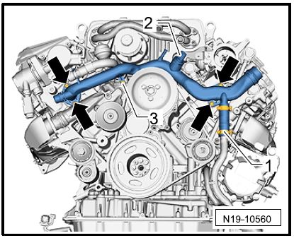
- Remove front coolant pipe ⇒Front coolant pipe.
Blue – Front coolant pipe
- – Hose clamp
- – Electric plug connection on coolant temperature sensor
- – Screw securing coolant pipe to thermostat housing
arrows – Fastening screws for coolant pipe
The procedure for removing the front coolant pipe is described in ⇒Workshop Manual ‘196120 Removing and installing coolant pipes’.
Front coolant pipe
Information
Only the sections “Removing front left coolant pipes” and “Removing front coolant pipe” in the Workshop Manual specified above are relevant for removing the front coolant pipe.
The front left coolant pipes must not be removed completely, but should only be loosened as far as required to allow access for removing and installing the front coolant pipe.
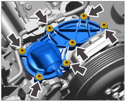
For instructions, see ⇒Workshop Manual ‘195819
Removing and installing coolant regulator (thermostat)’.
Removing and installing coolant regulator
- Install front coolant pipe ⇒Workshop Manual ‘196120 Removing and installing coolant pipes’.
- Remove lower part of intake manifold for cylinders 1-3 and 4-6 together with the fuel rail.
For instructions, see ⇒Workshop Manual ‘244719 Removing and installing intake manifold’, as well as the next step:
- Before loosening the fastening screws and nuts on lower part of intake manifold for cylinders 4-6, loosen the fuel pressure sensor at the fuel rail.
Information
The vacuum actuators for intake manifold flap control remain on the lower parts of the intake manifold. The description for replacing the vacuum actuators, which is also included in the Workshop Manual, is not relevant in this case.
- Replace both fuel rails.
Information
The steps described below – unless explicitly described for one specific lower part of intake manifold – must be carried out on lower part of intake manifold for cylinders 1-3 and on lower part of intake manifold for cylinders 4-6.
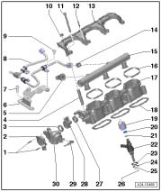
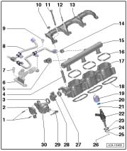
10.1 Unscrew fastening screw ⇒Assembly overview – lower part of intake manifold -12- on retaining bar for the fuel rail ⇒Assembly overview – lower part of intake manifold -13- and remove retaining bar from lower part of intake manifoldAssembly overview – lower part of intake manifold -17-.
10.2 Remove fuel rail ⇒Assembly overview – lower part of intake manifold -15- from lower part of intake manifold.
10.3 Screw new union fittings, Part No. 000.043.303.57 ⇒Assembly overview lower part of intake manifold -14-, hand-tight into the new fuel rails from the parts kit 000.043.303.51.
Check that the union fittings are fitted at the correct position. Do not tighten union fittings until lower part of intake manifold has been installed.
Assembly overview – lower part of intake manifold
10.4 Screw in fuel pressure sensor ⇒Assembly overview – lower part of intake manifold -5- on the new fuel rail for cylinders 4-6 hand-tight.
Do not tighten fuel pressure sensor until lower part of intake manifold has been installed.
10.5 Position new fuel rails on the relevant lower part of intake manifold.
10.6 Fit retaining bar for fuel rail ⇒Assembly overview – lower part of intake manifold -13- on lower part of intake manifold and only screw in the fastening screw ⇒Assembly overview lower part of intake manifold -12- as far as required so that the fuel rail can still be moved.
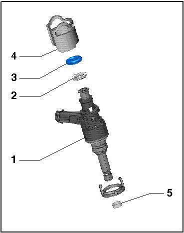
- Replace support piece as well as the support ring and sealing ring on all six fuel injectors ⇒Overview of fuel injector.
- – Fuel injector (remains in the cylinder head)
- – Support ring (replace, contained in gasket set 000.043.303.49)
- – Sealing ring (replace, contained in gasket set 000.043.303.49)
- – Support piece (replace, Part No. 000.043.303.50)
- – Sealing ring (replace only if the fuel injector was pulled out of the cylinder head; contained in gasket set 000.043.303.49)
The support piece ⇒Overview of fuel injector -4- as well as the support ring and sealing ring ⇒Overview of fuel injector -2 and 3- can be replaced when the fuel injector is installed. There is no need to remove the fuel injectors ⇒Overview of fuel injector -1- to do this. The support piece can be pulled up off the installed fuel injector.
Overview of fuel injector
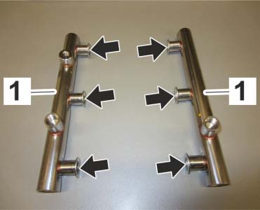
- Coat the pockets ⇒Fuel rails -arrows- on the new fuel rails ⇒Fuel rails -1- with clean engine oil before installing lower parts of intake manifold.
Fuel rails
- Install lower part of intake manifold for cylinders 1-3 and 4-6 together with the new fuel rail. For instructions, see ⇒Workshop Manual ‘244719 Removing and installing intake manifold’ and also pay particular attention to the following points:
- After fitting the fuel rails on the fuel injectors but before securing lower part of intake manifold, tighten the fastening screw ⇒Assembly overview – lower part of intake manifold -12- on the retaining bar for the fuel rails for cylinders 1-3 and 4-6 to prevent strain on the components. Tightening torque 2.5 Nm (2 ftlb.)
- Before re-fitting the fuel high-pressure lines ⇒Assembly overview – lower part of intake manifold -8-, tighten the union fittings ⇒ Assembly overview – lower part of intake manifold -14- on the fuel rails using a suitable open-end insert (a/f 19) for torque wrench. Tightening torque 40 Nm (30ftlb.)
Assembly overview – lower part of intake manifold
- Tighten fuel pressure sensor ⇒Assembly overview – lower part of intake manifold -5- at the fuel rail for cylinders 4-6 using a suitable open-end insert (a/f 27) for torque wrench. Tightening torque 22 Nm (16 ftlb.)
- For other tightening torques, see ⇒Workshop Manual ‘1001IN Tightening torques, tightening sequences, assembly overviews’.
- Install compressor ⇒Workshop Manual ‘211419 Removing and installing compressor’.
- Install poly-V-belt for compressor ⇒Workshop Manual ‘137819 Removing and installing drive belt’.
- Fill and bleed the cooling system ⇒Workshop Manual ‘193817 Draining and filling coolant (includes bleeding)’.
- Install engine cover.
- Install engine guard ⇒Workshop Manual ‘108019 Removing and installing engine guard’.
- Enter the recall campaign in the Warranty and Maintenance booklet.
References:
⇒Workshop Manual ‘1001IN Tightening torques, tightening sequences, assembly overviews’
⇒Workshop Manual ‘108019 Removing and installing engine guard’
⇒Workshop Manual ‘137819 Removing and installing drive belt’
⇒Workshop Manual ‘211419 Removing and installing compressor’
⇒Workshop Manual ‘196120 Removing and installing coolant pipes’
⇒Workshop Manual ‘195819 Removing and installing coolant regulator (thermostat)’
⇒Workshop Manual ‘244719 Removing and installing intake manifold’
⇒Workshop Manual ‘193817 Draining and filling coolant (includes bleeding)’
Attachment “B”:
Claim Submission – Recall Campaign AF03 Warranty claims should be submitted via WWS/PQIS.
Open campaigns may be checked by using either the PIWIS Vehicle Information system or through PQIS Job Creation.
Labor, parts, and sublet will be automatically inserted when Technician is selected in WWS/PQIS. If necessary, the required part numbers will need to be manually entered into warranty system by the dealer administrator.
Scope 1:
Not valid for these vehicle types
Scope 2:
Cayenne S Hybrid
| Working time:
Replacing both fuel rails and replacing support piece as well as the support ring and sealing ring on the fuel injectors; also replacing the coolant regulator Includes: Removing and installing engine guard Removing and installing engine cover | Labor time: 461 TU | |
| Parts required: | ||
|---|---|---|
| 000.043.303.51 | Fuel rail set | 1 ea. |
| 000.043.303.49 | Gasket set | 6 ea. |
| 000.043.303.50 | Support piece | 6 ea. |
| 000.043.303.57 | Union fitting | 2 ea. |
| 000.043.303.52 | Breather pipe | 1 ea. |
| 000.043.303.56 | Seal | 6 ea. |
| 000.043.303.58 | Seal | 6 ea. |
| 000.043.303.59 | Thermostat housing | 1 ea. |
| 000.043.303.53 | Seal | 1 ea. |
| 000.043.303.54 | Seal | 2 ea. |
| Additional materials required: | ||
| 000.043.301.48 | Antifreeze, 20-liter container | 0.08 ea. (= approx. 1.5 liters) |
| ⇒Damage code AF03 099 000 2 | ||
 Loading...
 Loading...
 Loading...
 Loading...
 Loading...
 Loading...
 Loading...
