| “This site contains affiliate links for which OEMDTC may be compensated” |
NHTSA Campaign Number: 17V054
Manufacturer Porsche Cars North America, Inc.
Components FUEL SYSTEM, GASOLINE
Potential Number of Units Affected 4,090
Fuel Leak due to Sheared Fastening Screws
A fuel leak in the presence of an ignition source increases the risk of a fire.
Summary
Porsche Cars North America, Inc. (Porsche
 ) is recalling certain 2017 911 Carrera, 911 Carrera S, 911 Carrera 4, 911 Carrera 4S, 911 Targa 4, 911 Targa 4S + GTS, 911 Carrera Cabriolet, 911 Carrera S Cabriolet, 911 Carrera 4 Cabriolet, 911 Carrera 4S Cabriolet, 718 Boxster, 718 Boxster S, 718 Cayman, and 718 Cayman S vehicles.
The screws that fasten the fuel collection pipes in the engine compartment may shear off, resulting in a fuel leak.
Remedy
Porsche will notify owners, and dealers will install improved fastening screws, free of charge.
The manufacturer has not yet provided a notification schedule.
Owners may contact Porsche customer service at 1-800-767-7243.
Porsche ’s number for this recall is AH01.
Notes
Owners may also contact the National Highway Traffic Safety Administration Vehicle Safety Hotline at 1-888-327-4236 (TTY 1-800-424-9153), or go to www.safercar.gov.
Check if your Porsche has a Recall
| Technical Information | Service |
2 |
| 13/17 ENU AH01 2 |
AH01 – Replacing Fastening Screws for Fuel Collection Pipes (Stop-Sale Campaign)
| Vehicle Type: | 718 Boxster (982)/718 Boxster S (982) |
| Model Year: | 2017 |
| Subject: | Fastening screws for fuel collection pipes |
| Concern: | There is a possibility that the fastening screws for the fuel collection pipes on the affected vehicles can shear off due to stress corrosion cracking.
If this happens, the high fuel pressure that builds up in the fuel injection system when the engine is running can press the relevant fuel collection pipe off the fuel injectors. This can cause a fuel leak in the engine compartment. |
| Remedial Action: | Replace fastening screws for both fuel collection pipes. |
| Parts Info: | NOTE: NECESSARY PARTS FOR THIS CAMPAIGN ARE STILL BEING MANUFACTURED AND ARE EXPECTED TO ARRIVE CW07. ONCE THE REQUIRED PARTS FOR THIS CAMPAIGN HAVE ARRIVED,
PCNA WILL BEGIN THE AUTOMATIC ALLOCATION PROCESS FOR UP TO 50% OF THE VEHICLES THAT ARE SERVICED AT YOUR DEALERSHIP. APPROXIMATELY 45 DAYS AFTER YOUR FIRST ALLOCATION, YOUR DEALER WILL AUTOMATICALLY BE ALLOCATED AN ADDITIONAL 30% OF THE REQUIRED PARTS FOR THE VEHICLES THAT ARE STILL IN NEED OF REPAIR. |
Installation
Position:
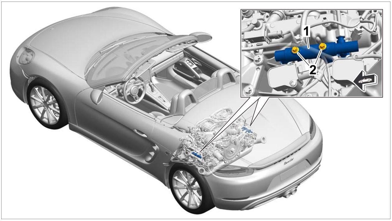
Overview of installation position (shown on 718 Boxster as an example)
1 – Fuel collection pipe
2 – Fastening screws (replace)
| Affected Vehicles: | Only the vehicles assigned to the campaign (see also PIWIS Vehicle information). This campaign affects 4,518 vehicles in North America. |
Parts required
| Parts Info: | Part No. | Designation – Use | Qty. |
| 000 043 306 00 | ⇒Torx screw, BM 6 x 85
– Fuel collection pipe | 4 ea. | |
| 999 076 053 01 | ⇒Hexagon nut, M10 – Rear diagonal brace | 8 ea. | |
| 999 072 840 01 | ⇒Hexagon-head bolt, M10 x 35
– Diagonal brace to body | 2 ea. | |
| N 908 484 05 | ⇒Hexagon nut, M12 x 1.5 – Engine carrier to engine mount | 2 ea. |
Required tools
| Tools: |
|
| |
| |
| |
| |
| |
| |
| |
| |
| |
| If the wheel alignment values must be corrected during suspension alignment, the following tools will also be required: | |
| |
| |
| |
| |
| |
|
Preparatory work
Work Procedure:
- Raise the vehicle on a lifting platform ⇒Workshop Manual ‘4X00IN Lifting the vehicle’.
- Move convertible top to service position ⇒Workshop Manual ‘6101IN Convertible-top service position’.
- Relieve fuel pressure in the system.
3.1 Remove cover on the fuse carrier in the passenger compartment at the front left.
3.2 Pull out fuse for fuel pump.
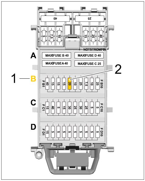
The fuse (20 A) is in row B ⇒Fuse carrier in passenger compartment at the front left -1-, slot FB5 ⇒Fuse carrier in passenger compartment at the front left -2-.
Fuse carrier in passenger compartment at the front left
WARNING
Exhaust gases
- Risk of Carbon Monoxide (CO) Poisoning
⇒Before starting the engine, position an exhaust extraction system behind the vehicle’s exhaust pipes and switch it on.
3.3 Start the engine and leave it running at idle speed until it cuts out.
This can take up to 5 minutes.
3.4 Switch off ignition and remove ignition key.
3.5 Re-insert fuse for fuel pump.
- Disconnect ground line at the battery ⇒Workshop Manual ‘2X00IN Work instructions after disconnecting the battery’.
- Remove trim panel for convertible top compartment ⇒Workshop Manual ‘700819 Removing and installing trim panel for convertible top compartment/engine compartment lid’.
- Remove engine compartment lid ⇒Workshop Manual ‘557819 Removing and installing engine compartment lid’.
- Remove air cleaner housing ⇒Workshop Manual ‘242519 Removing and installing air cleaner housing’.
- Remove rear wheels ⇒Workshop Manual ‘440519 Removing and reinstalling wheel’.
- Remove cover for rear underbody ⇒Workshop Manual ‘519419 Removing and installing cover for rear underbody’.
- Remove diagonal braces on the rear axle ⇒Workshop Manual ‘421320 Removing and installing struts’.
Replacing fastening screws for fuel collection pipes
Work Procedure:
- Lowering the engine to complete other work.
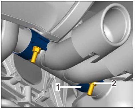
1.1 Loosen fastening nuts ⇒Turning tailpipe cover -2- on both clamps ⇒Turning tailpipe cover -1- for the tailpipe cover and turn the tailpipe cover as far as required until the tailpipes are pointing downwards.
Information
- The weight must be distributed uniformly on the oil pan.
- Never apply localised pressure to the oil pan
Turning tailpipe cover
1.2 Support the engine at the oil pan using a suitable transmission jack.
Information
- When lowering the engine, it must not rest on the rear-axle cross member.
- The exhaust system must not touch against the body or rear apron when lowering it.
- Always be careful of hoses, lines and cables when lowering the system!
- Always avoid collisions!
1.3 Lower the engine as far as required until the fastening screws for the fuel collection pipes are accessible.
For instructions, see ⇒Workshop Manual ‘1001IN Lowering the engine to complete other work’.
- Replace fastening screws for fuel collection pipes.
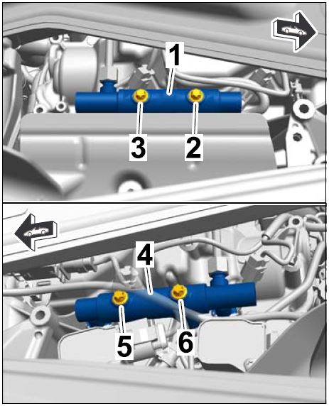
2.1 Loosen and unscrew front fastening screw ⇒Replacing fastening screws -2- (viewed in direction of travel) for fuel collection pipe on cylinder 1–3 ⇒Replacing fastening screws -1-.
2.2 Screw in and tighten new fastening screw, Part No. 000 043 306 00.
Tightening torque 13 Nm (9.5 ftlb.)
2.3 Loosen and unscrew rear fastening screw ⇒Replacing fastening screws -3- for fuel collection pipe on cylinder 1–3 ⇒Replacing fastening screws -1-.
2.4 Screw in and tighten new fastening screw, Part No. 000 043 306 00.
Tightening torque 13 Nm (9.5 ftlb.)
2.5 Repeat steps 3.1 to 3.4 on the fuel collection pipe on cylinder 4–6 ⇒Replacing fastening screws -4- in order to replace the fastening screws ⇒Replacing fastening screws -5 and 6-.
Replacing fastening screws
- Raise the engine to installation position and secure it.
For instructions, see ⇒Workshop Manual ‘1001IN Lowering the engine to complete other work’.
- Turn tailpipe cover into installation position and align it with respect to the rear apron. Then secure the tailpipe cover.
For instructions, see ⇒Workshop Manual ‘263519 Removing and installing tailpipe cover’.
Concluding work
Work Procedure:
- Install diagonal braces on the rear axle ⇒Workshop Manual ‘421320 Removing and installing struts’.
- Install cover for rear underbody ⇒Workshop Manual ‘519419 Removing and installing cover for rear underbody’.
- Install rear wheels ⇒Workshop Manual ‘440519 Removing and reinstalling wheel’.
- Install air cleaner housing ⇒Workshop Manual ‘242519 Removing and installing air cleaner housing’.
- Install engine compartment lid ⇒Workshop Manual ‘557819 Removing and installing engine compartment lid’.
- Install trim panel for convertible top compartment ⇒Workshop Manual ‘700819 Removing and installing trim panel for convertible top compartment/engine compartment lid’.
- Connect ground line for battery ⇒Workshop Manual ‘2X00IN Work instructions after disconnecting the battery’.
- Bleed the high-pressure side of the fuel system.
8.1 Connect a battery charger or power supply, suitable for AGM type batteries, recommended current rating of 70A fixed voltage 13.5V to 14.5V.
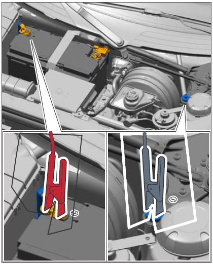
First connect the positive cable of the charger to the positive terminal of the battery and then connect the negative cable of the charger to the ground point for jump-lead starting ⇒External power connection.
Then switch on the battery charger and start charging the battery.
External power connection
8.2 Switch on the ignition.
8.3 Connect the PIWIS Tester to the vehicle communication module (VCI) via the USB cable. Then connect the communication module to the vehicle and switch on the PIWIS Tester.
8.4 On the PIWIS Tester start screen, call up the ‘Diagnostics’
The vehicle type is then read out, the diagnostic application is started and the control unit selection screen is populated.
8.5 Bleed the high-pressure side of the fuel system using the PIWIS Tester ⇒Workshop Manual ‘200107 Bleeding fuel system on high-pressure side – First start function’.
8.6 Read out and erase the fault memory ⇒Workshop Manual ‘033500 Fault memory for on-board diagnosis’.
Information
If control units are found to have faults that are not related to this workshop campaign, these must be found and corrected separately. This work cannot be invoiced under the workshop campaign number.
8.7 Switch off the ignition.
8.8 Disconnect the PIWIS Tester from the vehicle.
8.9 Switch off and disconnect the battery charger.
- Move convertible top out of service position ⇒Workshop Manual ‘6101IN Convertible-top service position’.
- Remove the vehicle from the lifting platform.
- Perform suspension alignment and make adjustments.
⇒Workshop Manual ‘449503 Suspension alignment, complete’
⇒Workshop Manual ‘4495TW Adjustment values for suspension alignment’
- After correcting the wheel alignment values, carry out the following required subsequent work.
12.1 Calibrate steering-angle sensor ⇒Workshop Manual ‘456005 Initialising and calibrating PSM steering-angle sensor’.
12.2 Teach steering lock settings for the power-steering gear ⇒Workshop Manual ‘489025 Power-steering gear: Teaching steering lock settings’.
12.3 If installed: Calibrate control unit for distance measuring sensor (ACC)Workshop Manual ‘278515 Adjusting control unit for distance measuring sensor’.
12.4 If installed: Calibrate front camera.
For instructions, see ⇒Workshop Manual ‘963855 Replacing front camera’.
- Enter the campaign in the Warranty and Maintenance booklet.
References:
⇒Workshop Manual ‘033500 Fault memory for on-board diagnosis’
⇒Workshop Manual ‘1001IN Lowering the engine to complete other work’
⇒Workshop Manual ‘2X00IN Work instructions after disconnecting the battery’
⇒Workshop Manual ‘200107 Bleeding fuel system on high-pressure side – First start function’
⇒Workshop Manual ‘242519 Removing and installing air cleaner housing’
⇒Workshop Manual ‘263519 Removing and installing tailpipe cover’
⇒Workshop Manual ‘278515 Adjusting control unit for distance measuring sensor’
⇒Workshop Manual ‘4X00IN Lifting the vehicle’
⇒Workshop Manual ‘421320 Removing and installing struts’
⇒Workshop Manual ‘440519 Removing and installing wheel’
⇒Workshop Manual ‘4495TW Adjustment values for suspension alignment’
⇒Workshop Manual ‘449503 Suspension alignment, complete’
⇒Workshop Manual ‘456005 Initialising and calibrating PSM steering-angle sensor’
⇒Workshop Manual ‘489025 Power-steering gear: Teaching steering lock settings’
⇒Workshop Manual ‘519419 Removing and installing cover for rear underbody’
⇒Workshop Manual ‘557819 Removing and installing engine compartment lid’
⇒Workshop Manual ‘6101IN Convertible-top service position’
⇒Workshop Manual ‘700819 Removing and installing trim panel for convertible top compartment/engine compartment lid’
⇒Workshop Manual ‘963855 Replacing front camera’
Warranty processing
Information:
Scope 1 – Scope 6: Not relevant for this vehicle type.
Information
The working times specified below were determined specifically for carrying out this campaign and may differ from the working times published in the Labor Operation List in PIWIS.
Scope 7:
Replacing fastening screws for fuel collection pipes
Vehicle equipment:
- without adaptive cruise control ACC
- without front camera
| Working time: | Replacing fastening screws for fuel collection pipes | Labor time: 465 TU |
| Includes: | Raising and lowering the vehicle
Moving convertible top into service position Reducing fuel pressure Disconnecting and connecting battery Removing and installing trim panel for convertible top compartment Removing and installing engine compartment lid Removing and installing air cleaner housing Removing and installing rear wheels Removing and installing cover for rear underbody Removing and installing diagonal braces Loosening and securing tailpipe cover Loosening and securing engine Connecting and disconnecting battery charger Connecting and disconnecting PIWIS Tester Bleeding fuel high-pressure system Reading out and erasing fault memory Performing suspension alignment and making adjustments Calibrating steering-angle sensor Teaching steering lock settings | |
| Without: | Calibrating control unit for distance measuring sensor
Calibrating front camera | |
| Parts required: | ||
| 000 043 306 00 | Torx screw, BM 6 x 85
– Fuel collection pipe | 4 ea. |
| 999 076 053 01 | Hexagon nut, M10
– Rear diagonal brace | 8 ea. |
| 999 072 840 01 | Hexagon-head bolt, M10 x 35
– Diagonal brace to body | 2 ea. |
| N 908 484 05 | Hexagon nut, M12 x 1.5 | 2 ea. |
| ⇒Damage Code AH01 099 000 2 | ||
Scope 8:
Replacing fastening screws for fuel collection pipes
Vehicle equipment:
- Adaptive cruise control ACC (I-no. 456) and/or front camera (I-no. 631, 632 or 852)
| Working time: | Replacing fastening screws for fuel collection pipes | Labor time: 515 TU |
| Includes: | Raising and lowering the vehicle
Moving convertible top into service position Reducing fuel pressure Disconnecting and connecting battery Removing and installing trim panel for convertible top compartment Removing and installing engine compartment lid Removing and installing air cleaner housing Removing and installing rear wheels Removing and installing cover for rear underbody Removing and installing diagonal braces Loosening and securing tailpipe cover Loosening and securing engine Connecting and disconnecting battery charger Connecting and disconnecting PIWIS Tester Bleeding fuel high-pressure system Reading out and erasing fault memory Performing suspension alignment and making adjustments Calibrating steering-angle sensor Teaching steering lock settings Calibrating control unit for distance measuring sensor Calibrating front camera | |
| Parts required: | ||
| 000 043 306 00 | Torx screw, BM 6 x 85
– Fuel collection pipe | 4 ea. |
| 999 076 053 01 | Hexagon nut, M10
– Rear diagonal brace | 8 ea. |
| 999 072 840 01 | Hexagon-head bolt, M10 x 35
– Diagonal brace to body | 2 ea. |
| N 908 484 05 | Hexagon nut, M12 x 1.5 | 2 ea. |
| ⇒Damage Code AH01 099 000 2 | ||
 Loading...
